描述
RouterOS支持在一台路由器上创建多个Virtual Routing and Forwarding实例。这对于基于bgp的MPLS vpn非常有用。与OSI第二层技术BGP VPLS不同,BGP VRF vpn工作在第三层,并在路由器之间交换IP前缀。vrf解决了IP前缀重叠的问题,并提供了所需的隐私(通过不同vpn的分离路由)。
可以建立VRF -lite设置或使用VPNv4地址族的多协议BGP从VRF路由表分发路由——不仅分发给其他路由器,而且分发给路由器本身的不同路由表。
配置
VRF表在 /ip VRF 菜单中创建。VRF配置完成后,添加路由表映射(创建一个同名的动态表)。每个活动VRF总是有一个映射的路由表。
[admin@arm-bgp] /ip/vrf> print
Flags: X - disabled; * - builtin
 0  * name="main" interfaces=all

[admin@arm-bgp] /routing/table> print
Flags: D - dynamic; X - disabled, I - invalid; U - used
 0 D   name="main" fib
注意,添加的vrf的顺序很重要。要正确匹配哪个接口将属于VRF,必须注意将VRF按正确的顺序放置(匹配从顶部条目开始,就像防火墙规则一样)。
由于每个VRF都映射了路由表,所以最大唯一VRF的数量也被限制为4096。
请看下面的例子:
[admin@arm-bgp] /ip/vrf> print
Flags: X - disabled; * - builtin
 0  * name="main" interfaces=all
 1    name="myVrf" interfaces=lo_vrf
因为第一个表项匹配所有接口,所以第二个VRF不会添加任何接口。要解决这个问题,必须更改条目的顺序。
[admin@arm-bgp] /ip/vrf> move 1 0
[admin@arm-bgp] /ip/vrf> print
Flags: X - disabled; * - builtin
 0    name="myVrf" interfaces=lo_vrf
 1  * name="main" interfaces=all
分配到VRF的接口所连接的路由会自动安装到相应的路由表中。
当接口被分配给VRF以及连接的路由时,这并不意味着RouterOS服务仅仅通过在配置中指定IP地址就能神奇地知道使用哪个VRF。每个服务都需要添加VRF支持并进行显式配置。服务是否支持VRF并具有VRF配置选项,请参考相应的服务文档。
例如,创建一个SSH服务来监听属于VRF的接口上的连接:
[admin@arm-bgp] /ip/service> set ssh vrf=myVrf
[admin@arm-bgp] /ip/service> print
Flags: X, I - INVALID
Columns: NAME, PORT, CERTIFICATE, VRF
#   NAME     PORT  CERTIFICATE  VRF
0   telnet     23               main
1   ftp        21
2   www        80               main
3   ssh        22               myVrf
4 X www-ssl   443  none         main
5   api      8728               main
6   winbox   8291               main
7   api-ssl  8729  none         main
向VRF添加路由非常简单,只需在添加路由时指定路由表参数,并在网关IP后指定@name,指定在哪个路由表中解析网关即可。
/ip route add dst-address=192.168.1.0/24 gateway=172.16.1.1@myVrf routing-table=myVrf
如果网关被显式设置为在另一个VRF中解析,则可能在VRF之间发生流量泄漏,例如:
# add route in the myVrf, but resolve the gateway in the main table
/ip route add dst-address=192.168.1.0/24 gateway=172.16.1.1@main routing-table=myVrf

# add route in the main table, but resolve the gateway in the myVrf
/ip route add dst-address=192.168.1.0/24 gateway=172.16.1.1@myVrf
如果网关配置没有显式配置的表来解析,则认为网关应该在“main”表中解析。
支持的功能
不同的服务可以放置在特定的VRF中,服务在VRF上监听传入连接或创建传出连接。默认情况下,所有服务都使用“main”表,但可以使用单独的“vrf”参数或在IP地址末尾指定以“@”分隔的vrf名称来更改。
下面是受支持的服务列表。
| Feature | Support | Comment | |
|---|---|---|---|
| BGP | + |
|
|
| + |
|
||
| IP Services | + | VRF is supported for telnet, www, ssh, www-ssl, api, winbox, api-ssl services. The ftp service does not support changing the VRF.
|
|
| L2TP Client | + |
|
|
| MPLS | + |
|
|
| Netwatch | + |
|
|
| NTP | + |
|
|
| OSPF | + |
|
|
| ping | + |
|
|
| RADIUS | + |
|
|
| RIP | + |
|
|
| RPKI | + |
|
|
| SNMP | + |
|
|
| EoIP | + |
|
|
| IPIP | + |
|
|
| GRE | + |
|
|
| SSTP-client | + |
|
|
| OVPN-client | + |
|
|
| L2TP-ether | + |
|
|
| VXLAN | + |
|
例子
简单的VRF-Lite设置
考虑一个设置,其中需要两个需要访问互联网的客户vrf:
/ip address
add address=172.16.1.2/24 interface=public
add address=192.168.1.1/24 interface=ether1
add address=192.168.2.1/24 interface=ether2

/ip route
add gateway=172.16.1.1

# add VRF configuration
/ip vrf
add name=cust_a interface=ether1 place-before 0
add name=cust_b interface=ether2 place-before 0

# add vrf routes
/ip route
add gateway=172.16.1.1@main routing-table=cust_a
add gateway=172.16.1.1@main routing-table=cust_b

# masquerade local source
/ip firewall nat add chain=srcnat out-interface=public action=masquerade
可能有必要确保来自“公共”接口的数据包能够真正到达正确的VRF。 这可以通过标记VRF客户发起的新连接来解决,并通过“公共”接口上传入数据包的路由标记来引导流量。
# mark new customer connections
/ip firewall mangle
add action=mark-connection chain=prerouting connection-state=new new-connection-mark=\
    cust_a_conn src-address=192.168.1.0/24 passthrough=no
add action=mark-connection chain=prerouting connection-state=new new-connection-mark=\
    cust_b_conn src-address=192.168.2.0/24 passthrough=no

# mark routing
/ip firewall mangle
add action=mark-routing chain=prerouting connection-mark=cust_a_conn \
    in-interface=public new-routing-mark=cust_a
add action=mark-routing chain=prerouting connection-mark=cust_b_conn \
    in-interface=public new-routing-mark=cust_b
静态vrf间路由
一般情况下,建议所有VRF之间的路由都使用BGP本地导入和导出功能进行交换。如果这还不够,还可以使用静态路由来实现这种所谓的路由泄漏。
有两种方法可以安装路由,使其网关位于与路由本身不同的路由表中。
第一种方法是在添加路由时在gateway字段中显式指定路由表。这只有在将路由和网关从“主”路由表泄漏到另一个路由表(VRF)时才有可能。例子:
# add route to 5.5.5.0/24 in 'vrf1' routing table with gateway in the main routing table
add dst-address=5.5.5.0/24 gateway=10.3.0.1@main routing-table=vrf1
第二种方法是在gateway字段中显式指定接口。指定的接口可以属于VRF实例。例子:
# add route to 5.5.5.0/24 in the main routing table with gateway at 'ether2' VRF interface
add dst-address=5.5.5.0/24 gateway=10.3.0.1%ether2 routing-table=main
# add route to 5.5.5.0/24 in the main routing table with 'ptp-link-1' VRF interface as gateway
add dst-address=5.5.5.0/24 gateway=ptp-link-1 routing-table=main
可以看到,有两种可能的变化—将网关指定为 ip_address%interface 或简单地指定一个 interface_。在大多数情况下,前者应该用于广播接口。第二种应该用于点到点接口,如果路由是某个VRF中的连通路由,也可以用于广播接口。例如,如果你在接口 _ether2 上有一个地址' 1.2.3.4/24 ',它被放在一个VRF中,那么在这个VRF的路由表中就会有一条到' 1.2.3.0/24 '的连接路由。在不同的路由表中添加静态路由' 1.2.3.0/24 '是可以接受的,即使 ether2 是一个广播接口:
add dst-address=1.2.3.0/24 gateway=ether2 routing-table=main
最简单的MPLS VPN设置
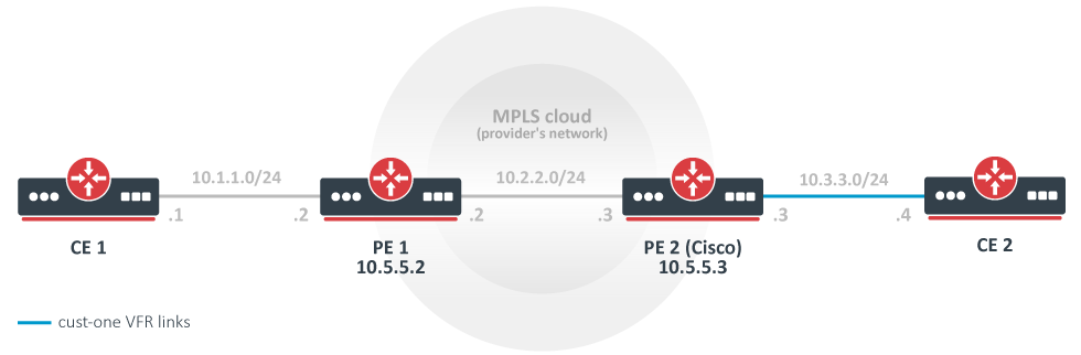
在本例中,创建并配置一个基本的MPLS骨干网(由两个PE路由器PE1和PE2组成),用于转发属于 customer -one VPN的CE路由器CE1和CE2之间的流量。
CE1路由器
/ip address add address=10.1.1.1/24 interface=ether1
# use static routing
/ip route add dst-address=10.3.3.0/24 gateway=10.1.1.2
CE2路由器
/ip address add address=10.3.3.4/24 interface=ether1
/ip route add dst-address=10.1.1.0/24 gateway=10.3.3.3
PE1路由器
/interface bridge add name=lobridge
/ip address add address=10.1.1.2/24 interface=ether1
/ip address add address=10.2.2.2/24 interface=ether2
/ip address add address=10.5.5.2/32 interface=lobridge
/ip vrf add name=cust-one interfaces=ether1
/mpls ldp add enabled=yes transport-address=10.5.5.2 lsr-id=10.5.5.2
/mpls ldp interface add interface=ether2
/routing bgp template set default as=65000

/routing bgp vpn
add vrf=cust-one \
  route-distinguisher=1.1.1.1:111 \
  import.route-targets=1.1.1.1:111 \
  import.router-id=cust-one \
  export.redistribute=connected \
  export.route-targets=1.1.1.1:111 \
  label-allocation-policy=per-vrf
/routing bgp connection
add template=default remote.address=10.5.5.3 address-families=vpnv4 local.address=10.5.5.2

# add route to the remote BGP peer's loopback address
/ip route add dst-address=10.5.5.3/32 gateway=10.2.2.3
PE2路由器(Cisco)
ip vrf cust-one
rd 1.1.1.1:111
route-target export 1.1.1.1:111
route-target import 1.1.1.1:111
exit

interface Loopback0
ip address 10.5.5.3 255.255.255.255

mpls ldp router-id Loopback0 force
mpls label protocol ldp

interface FastEthernet0/0
ip address 10.2.2.3 255.255.255.0
mpls ip

interface FastEthernet1/0
ip vrf forwarding cust-one
ip address 10.3.3.3 255.255.255.0

router bgp 65000
neighbor 10.5.5.2 remote-as 65000
neighbor 10.5.5.2 update-source Loopback0
address-family vpnv4
neighbor 10.5.5.2 activate
neighbor 10.5.5.2 send-community both
exit-address-family
address-family ipv4 vrf cust-one
redistribute connected
exit-address-family

ip route 10.5.5.2 255.255.255.255 10.2.2.2
结果
检查VPNv4路由重新分配是否正常工作:
[admin@PE1] /routing/route> print detail where afi="vpn4"
Flags: X - disabled, F - filtered, U - unreachable, A - active;
c - connect, s - static, r - rip, b - bgp, o - ospf, d - dhcp, v - vpn, m - modem, a - ldp-address, l - l
dp-mapping, g - slaac, y - bgp-mpls-vpn;
H - hw-offloaded; + - ecmp, B - blackhole
 Ab   afi=vpn4 contribution=active dst-address=111.16.0.0/24&;1.1.1.1:111 routing-table=main label=16
       gateway=111.111.111.4 immediate-gw=111.13.0.2%ether9 distance=200 scope=40 target-scope=30
       belongs-to="bgp-VPN4-111.111.111.4"
       bgp.peer-cache-id=*2C00011 .as-path="65511" .ext-communities=rt:1.1.1.1:111 .local-pref=100
       .atomic-aggregate=yes .origin=igp
       debug.fwp-ptr=0x202427E0

[admin@PE1] /routing/bgp/advertisements> print
 0 peer=to-pe2-1 dst=10.1.1.0/24 local-pref=100 origin=2 ext-communities=rt:1.1.1.1:111 atomic-aggregate=yes
检查IP路由表中是否安装了10.3.3.0版本,在cost -one路由表中:
[admin@PE1] > /ip route print where routing-table="cust-one"
Flags: D - DYNAMIC; A - ACTIVE; c, b, y - BGP-MPLS-VPN
Columns: DST-ADDRESS, GATEWAY, DISTANCE
# DST-ADDRESS     GATEWAY         DISTANCE
0 ADC 10.1.1.0/24 ether1@cust-one        0
1 ADb 10.3.3.0/24 10.5.5.3              20
仔细看看单VRF中的IP路由。10.1.1.0/24是已连接的路由,该路由属于已配置为cost - 1 VRF的接口。10.3.3.0/24 IP前缀作为VPNv4路由从PE2通过BGP发布,并被引入到VRF路由表中,因为配置的 import-route-targets 与发布时的BGP扩展团体属性相匹配。
[admin@PE1] /routing/route> print detail where routing-table="cust-one"
Flags: X - disabled, F - filtered, U - unreachable, A - active;
c - connect, s - static, r - rip, b - bgp, o - ospf, d - dhcp, v - vpn, m - modem, a - ldp-address, l - l
dp-mapping, g - slaac, y - bgp-mpls-vpn;
H - hw-offloaded; + - ecmp, B - blackhole
 Ac   afi=ip4 contribution=active dst-address=10.1.1.0/24 routing-table=cust-one
       gateway=ether1@cust-one immediate-gw=ether1 distance=0 scope=10 belongs-to="connected"
       local-address=10.1.1.2%ether1@cust-one
       debug.fwp-ptr=0x202420C0

 Ay   afi=ip4 contribution=active dst-address=10.3.3.0/24 routing-table=cust-one label=16
       gateway=10.5.5.3 immediate-gw=10.2.2.3%ether2 distance=20 scope=40 target-scope=30
       belongs-to="bgp-mpls-vpn-1-bgp-VPN4-10.5.5.3-import"
       bgp.peer-cache-id=*2C00011 .ext-communities=rt:1.1.1.1:111 .local-pref=100
       .atomic-aggregate=yes .origin=igp
       debug.fwp-ptr=0x20242840


[admin@PE1] /routing/route> print detail where afi="vpn4"
Flags: X - disabled, F - filtered, U - unreachable, A - active;
c - connect, s - static, r - rip, b - bgp, o - ospf, d - dhcp, v - vpn, m - modem, a - ldp-address, l - l
dp-mapping, g - slaac, y - bgp-mpls-vpn;
H - hw-offloaded; + - ecmp, B - blackhole
 Ay   afi=vpn4 contribution=active dst-address=10.1.1.0/24&;1.1.1.1:111 routing-table=main label=19
       gateway=ether1@cust-one immediate-gw=ether1 distance=200 scope=40 target-scope=10
       belongs-to="bgp-mpls-vpn-1-connected-export"
       bgp.ext-communities=rt:1.1.1.1:1111 .atomic-aggregate=no .origin=incomplete
       debug.fwp-ptr=0x202426C0

 Ab   afi=vpn4 contribution=active dst-address=10.3.3.0/24&;1.1.1.1:111 routing-table=main label=16
       gateway=10.5.5.3 immediate-gw=10.2.2.3%ether2 distance=200 scope=40 target-scope=30
       belongs-to="bgp-VPN4-10.5.5.3"
       bgp.peer-cache-id=*2C00011 .ext-communities=rt:1.1.1.1:111 .local-pref=100
       .atomic-aggregate=yes .origin=igp
       debug.fwp-ptr=0x202427E0
思科也是如此:
PE2#show ip bgp vpnv4 all
BGP table version is 5, local router ID is 10.5.5.3
Status codes: s suppressed, d damped, h history, * valid, > best, i - internal,
r RIB-failure, S Stale
Origin codes: i - IGP, e - EGP, ? - incomplete
Network Next Hop Metric LocPrf Weight Path
Route Distinguisher: 1.1.1.1:111 (default for vrf cust-one)
*>i10.1.1.0/24 10.5.5.2 100 0 ?
*> 10.3.3.0/24 0.0.0.0 0 32768 ?

PE2#show ip route vrf cust-one
Routing Table: cust-one
Codes: C - connected, S - static, R - RIP, M - mobile, B - BGP
D - EIGRP, EX - EIGRP external, O - OSPF, IA - OSPF inter area
N1 - OSPF NSSA external type 1, N2 - OSPF NSSA external type 2
E1 - OSPF external type 1, E2 - OSPF external type 2
i - IS-IS, su - IS-IS summary, L1 - IS-IS level-1, L2 - IS-IS level-2
ia - IS-IS inter area, * - candidate default, U - per-user static route
o - ODR, P - periodic downloaded static route

Gateway of last resort is not set
10.0.0.0/24 is subnetted, 1 subnets
B 10.1.1.0 [200/0] via 10.5.5.2, 00:05:33
10.0.0.0/24 is subnetted, 1 subnets
C 10.3.3.0 is directly connected, FastEthernet1/0
应该能从CE1 ping到CE2,反之亦然。
[admin@CE1] > /ping 10.3.3.4
10.3.3.4 64 byte ping: ttl=62 time=18 ms
10.3.3.4 64 byte ping: ttl=62 time=13 ms
10.3.3.4 64 byte ping: ttl=62 time=13 ms
10.3.3.4 64 byte ping: ttl=62 time=14 ms
4 packets transmitted, 4 packets received, 0% packet loss
round-trip min/avg/max = 13/14.5/18 ms
更复杂的设置(只能更改)
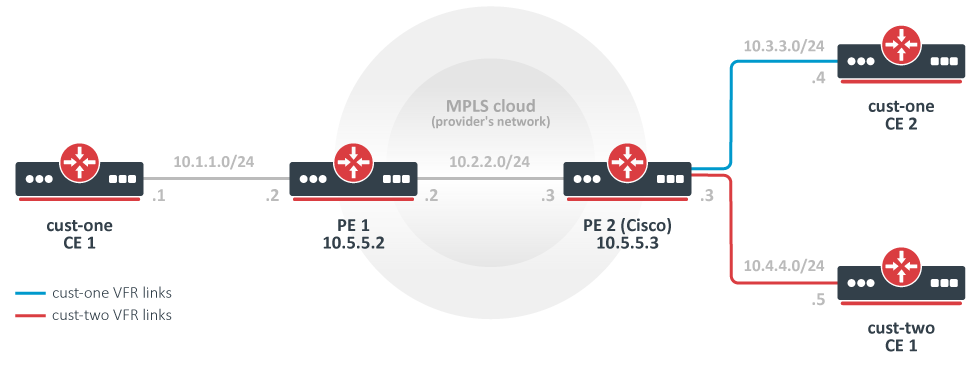
与最简单的设置相反,在本例中,有两个客户:客户1和客户2。
为它们配置了两个vpn,分别是cost - 1和cost - 2,并交换它们之间的所有路由。(这也被称为“路由泄漏”)。
注意,这可能不是最典型的设置,因为路由通常不会在不同的客户之间交换。相反,默认情况下,不可能从一个VRF站点访问另一个VPN中的另一个VRF站点。(这是vpn的“私有”方面。)分离路由是提供隐私的一种方式,也是解决IP网络前缀重叠问题所必需的。路由交换与这两个需求直接冲突,但有时可能需要(例如,当两个客户迁移到单个网络基础设施时,临时解决方案)。
CE1路由器,客户1
/ip route add dst-address=10.4.4.0/24 gateway=10.1.1.2
CE2路由器,客户1
/ip route add dst-address=10.4.4.0/24 gateway=10.3.3.3
CE1路由器,客户2
/ip address add address=10.4.4.5 interface=ether1
/ip route add dst-address=10.1.1.0/24 gateway=10.3.3.3
/ip route add dst-address=10.3.3.0/24 gateway=10.3.3.3
PE1路由器
# replace the old BGP VPN with this:
/routing bgp vpn
add vrf=cust-one \
  export.redistribute=connected \
  route-distinguisher=1.1.1.1:111 \
  import.route-targets=1.1.1.1:111,2.2.2.2:222  \
  export.route-targets=1.1.1.1:111
PE2路由器(Cisco)
ip vrf cust-one
rd 1.1.1.1:111
route-target export 1.1.1.1:111
route-target import 1.1.1.1:111
route-target import 2.2.2.2:222
exit

ip vrf cust-two
rd 2.2.2.2:222
route-target export 2.2.2.2:222
route-target import 1.1.1.1:111
route-target import 2.2.2.2:222
exit

interface FastEthernet2/0
ip vrf forwarding cust-two
ip address 10.4.4.3 255.255.255.0

router bgp 65000
address-family ipv4 vrf cust-two
redistribute connected
exit-address-family
变化:用另一台MT替换思科
PE2 Mikrotik配置
/interface bridge add name=lobridge
/ip address
add address=10.2.2.3/24 interface=ether1
add address=10.3.3.3/24 interface=ether2
add address=10.4.4.3/24 interface=ether3
add address=10.5.5.3/32 interface=lobridge
/ip vrf
add name=cust-one interfaces=ether2
add name=cust-two interfaces=ether3
/mpls ldp add enabled=yes transport-address=10.5.5.3
/mpls ldp interface add interface=ether1

/routing bgp template set default as=65000
/routing bgp vpn
add vrf=cust-one \
  export.redistribute=connected \
  route-distinguisher=1.1.1.1:111 \
  import.route-targets=1.1.1.1:111,2.2.2.2:222 \
  export.route-targets=1.1.1.1:111 \
add vrf=cust-two \
  export.redistribute=connected \
  route-distinguisher=2.2.2.2:222 \
  import.route-targets=1.1.1.1:111,2.2.2.2:222 \
  export.route-targets=2.2.2.2:222 \

/routing bgp connection
add template=default remote.address=10.5.5.2 address-families=vpnv4 local.address=10.5.5.3

# add route to the remote BGP peer's loopback address
/ip route add dst-address=10.5.5.2/32 gateway=10.2.2.2
结果
现在,/ip route print 的输出非常有趣,值得仔细观察。
[admin@PE2] /ip route> print
Flags: X - disabled, A - active, D - dynamic,
C - connect, S - static, r - rip, b - bgp, o - ospf, m - mme,
B - blackhole, U - unreachable, P - prohibit
# DST-ADDRESS PREF-SRC GATEWAY DISTANCE
0 ADb 10.1.1.0/24 10.5.5.2 recurs... 20
1 ADC 10.3.3.0/24 10.3.3.3 ether2 0
2 ADb 10.4.4.0/24 20
3 ADb 10.1.1.0/24 10.5.5.2 recurs... 20
4 ADb 10.3.3.0/24 20
5 ADC 10.4.4.0/24 10.4.4.3 ether3 0
6 ADC 10.2.2.0/24 10.2.2.3 ether1 0
7 A S 10.5.5.2/32 10.2.2.2 reacha... 1
8 ADC 10.5.5.3/32 10.5.5.3 lobridge 0
从远端BGP对等体接收到10.1.1.0/24路由,并安装在两个VRF路由表中。
路由10.3.3.0/24和10.4.4.0/24也安装在两个VRF路由表中。每条路由在一个表中是一条连接路由,在另一个表中是一条BGP路由。这与他们通过BGP发布通告无关。它们只是被“发布”到本地VPNv4路由表,然后在本地重新引入。Import和export route-targets 决定它们将在哪个表中结束。
这可以从它的属性中推断出来——它们不具有通常的BGP属性。(路线10.4.4.0/24。)
[admin@PE2] /routing/route> print detail where routing-table=cust-one ...
vrf间路由泄漏
目前,还没有机制可以将路由从一个VRF实例泄漏到同一路由器内的另一个VRF实例。
作为一种解决方案,可以在两个本地配置的环回地址之间创建隧道,并将每个隧道端点分配给自己的VRF。然后可以运行动态路由协议或设置静态路由在两个vrf之间泄漏。
这种方法的缺点是必须在每个VRF之间创建隧道,路由应该泄漏(创建一个完整的网格),这使得配置非常复杂,即使只有几个VRF,更不用说更复杂的设置了。
例如,要在5个vrf之间泄漏路由,需要n * (n - 1) / 2个连接,这将导致在一台路由器上设置20个隧道端点和20个OSPF实例。
使用该方法的两个vrf的配置示例:
/interface bridge
add name=dummy_custC
add name=dummy_custB
add name=lo1
add name=lo2

/ip address
add address=111.255.255.1 interface=lo1 network=111.255.255.1
add address=111.255.255.2 interface=lo2 network=111.255.255.2
add address=172.16.1.0/24 interface=dummy_custC network=172.16.1.0
add address=172.16.2.0/24 interface=dummy_custB network=172.16.2.0

/interface ipip
add local-address=111.255.255.1 name=ipip-tunnel1 remote-address=111.255.255.2
add local-address=111.255.255.2 name=ipip-tunnel2 remote-address=111.255.255.1

/ip address
add address=192.168.1.1/24 interface=ipip-tunnel1 network=192.168.1.0
add address=192.168.1.2/24 interface=ipip-tunnel2 network=192.168.1.0

/ip vrf
add interfaces=ipip-tunnel1,dummy_custC name=custC
add interfaces=ipip-tunnel2,dummy_custB name=custB

/routing ospf instance
add disabled=no name=i2_custB redistribute=connected,static,copy router-id=192.168.1.1 routing-table=custB vrf=custB
add disabled=no name=i2_custC redistribute=connected router-id=192.168.1.2 routing-table=custC vrf=custC
/routing ospf area
add disabled=no instance=i2_custB name=custB_bb
add disabled=no instance=i2_custC name=custC_bb
/routing ospf interface-template
add area=custB_bb disabled=no networks=192.168.1.0/24
add area=custC_bb disabled=no networks=192.168.1.0/24
结果:
[admin@rack1_b36_CCR1009] /routing/ospf/neighbor> print
Flags: V - virtual; D - dynamic
 0  D instance=i2_custB area=custB_bb address=192.168.1.1 priority=128 router-id=192.168.1.2 dr=192.168.1.1 bdr=192.168.1.2
      state="Full" state-changes=6 adjacency=41m28s timeout=33s

 1  D instance=i2_custC area=custC_bb address=192.168.1.2 priority=128 router-id=192.168.1.1 dr=192.168.1.1 bdr=192.168.1.2
      state="Full" state-changes=6 adjacency=41m28s timeout=33s


[admin@rack1_b36_CCR1009] /ip/route> print where routing-table=custB
Flags: D - DYNAMIC; A - ACTIVE; c, s, o, y - COPY
Columns: DST-ADDRESS, GATEWAY, DISTANCE
     DST-ADDRESS       GATEWAY                         DISTANCE
  DAo 172.16.1.0/24     192.168.1.1%ipip-tunnel2@custB       110
  DAc 172.16.2.0/24     dummy_custB@custB                      0
  DAc 192.168.1.0/24    ipip-tunnel2@custB                     0


[admin@rack1_b36_CCR1009] > /ip route/print where routing-table=custC
Flags: D - DYNAMIC; A - ACTIVE; c, o, y - COPY
Columns: DST-ADDRESS, GATEWAY, DISTANCE
    DST-ADDRESS       GATEWAY                         DISTANCE
  DAc 172.16.1.0/24     dummy_custC@custC                      0
  DAo 172.16.2.0/24     192.168.1.2%ipip-tunnel1@custC       110
  DAc 192.168.1.0/24    ipip-tunnel1@custC                     0
参考文献
RFC 4364: BGP/MPLS IP Virtual Private Networks (VPNs)
MPLS Fundamentals, chapter 7, Luc De Ghein, Cisco Press 2006